Test: Difference between revisions
| Line 56: | Line 56: | ||
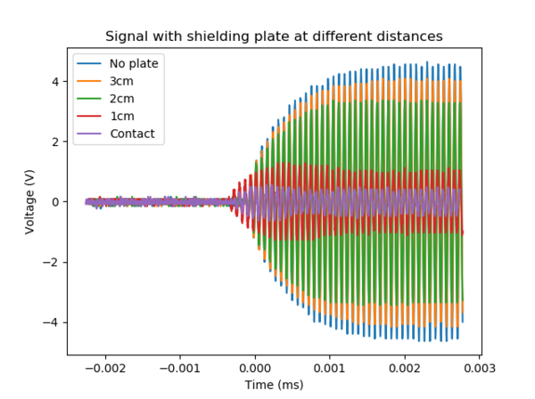
For this experiment, the receiver was kept almost in contact with the emitter while distance of the shield plate to the receiver, d is varied. | For this experiment, the receiver was kept almost in contact with the emitter while distance of the shield plate to the receiver, d is varied. | ||
[[File:E0271462_shielding vs distance.png|600px|thumb|center|Plot of Voltage picked up by receiver at different shield distances to the receiver/emitter]] | [[File:E0271462_shielding vs distance.png|600px|thumb|center|Plot of Voltage picked up by receiver at different shield distances to the receiver/emitter]] | ||
We could see that even if the plate is not between the receiver and emitter, the signal picked up is also reduced to some extent, providing a shielding effect for the receiver. For comparison, the actual RFID tag for the emitter was found to be functioning only when the shield plate is at least 3mm away from the RFID tag. This could allow to estimate the required Vpp to power the RFID tag which is approximately | We could see that even if the plate is not between the receiver and emitter, the signal picked up is also reduced to some extent, providing a shielding effect for the receiver. For comparison, the actual RFID tag/card for the emitter was found to be functioning only when the shield plate is at least 3mm away from the RFID tag. This could allow to estimate the required Vpp to power the RFID tag which is approximately 8V. | ||
In some cases, there were advice given to not use multiple cards on | In some cases, there were advice given to not use multiple cards on an emitter. Out of curiosity, we test the receiver along with an actual RFID tag/card meant for the receiver. | ||
[[File:E0271462_1card vs 2 card.png|600px|thumb|center| | [[File:E0271462_1card vs 2 card.png|600px|thumb|center|Comparison having the receiver alone and receiver with the actual RFID tag/card]] | ||
From the data, we can see that there is some attentuation due to the presence of a second card. However, it is not much and in this case, both changes to both 'cards' could have been made which is usually a non ideal outcome. | From the data, we can see that there is some attentuation due to the presence of a second card. However, it is not much and in this case, both changes to both 'cards' could have been made which is usually a non ideal outcome. | ||
Revision as of 14:43, 30 April 2022
Team members
Radio-Frequency and its applications
Radio-frequency (RF) is a part of the electromagnetic spectrum typically in the range from 10kHz to 300GHz. RF technology is an integral part of our everyday lives. Common examples include phone signals, radio broadcast, ID cards used for various public transport and access control (RFID), various forms of wireless payments which we know as NFC (Near Field Communication). More niche applications of RF would be control electronics, modulation of electro-optical components, ion traps etc.
In the case of RFIDs, there is usually an emitter and receiver. The emitter is usually connected to a power source and is constantly emitting a RF signal. This is known as an active component. The receiver on the other hand only has doesnt have a power supply and is usually powered by the RF wave produced by the emitter. It is also known as a passive component. In the receiver, there is also a microchip which stores data which can be extracted and transmitted through these RF waves back to the emitter to trigger certain actions.
Because most of the information transfer happens in the form of an EM wave, it can be transmitted through free space which removes the need for a physical electrical connection between users and hence the term 'Wireless'. However, just like how physical wired connections could be tapped to steal information or to manipulate data stored, such wireless technology is also susceptible to tampering.
To combat this, developments have been made to protect us from such tampering and the solution is to develop shields around the devices that prevent external EM waves from communicating with the device in the case of passive components.
Some properties which may or may not affect the shield strength would include:
- Conductivity of material
- Shape of material
- Thickness of material
- Frequency
Setup
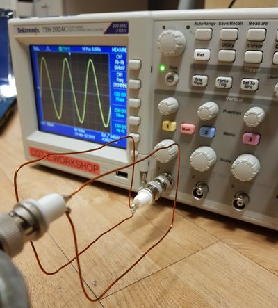
To learn about how effective a shield is to RF, we first need to emulate an emitter and a receiver. For the emitter we will be using a function generator (Tektronix AFG 3102) connected to a loop of wire. For the receiver we will be using a second loop of wire that has approximately the same dimensions as the receiver. This will then be connected to an oscilloscope to observe the pick up of the RF signal. The design of the loop of wire is complex and there are proper studies conducted to optimize design for the most effective transfer of EM signal. However, this is not the objective of the experiment and hence a simple wire loop with dimensions comparable to typical RFID tags (5.4cm x 8.6cm) will suffice.
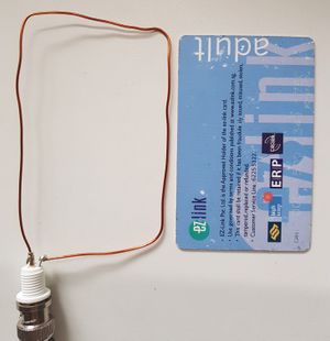
After the loops of wires are connected to their respective equipment, we then align both the loops of wire close to each other, maximizing the pick up signal from the receiver loop. However, a gap of 2cm is left intentionally between the 2 loops in order to leave room to insert shielding material. To quantify the strength of the signal picked up, we will be using the peak to peak voltage (Vpp) as a metric for the measurements performed.
The experimental sequence goes as follows:
Step 1: Choose a frequency value on the function generator and record Vpp on the oscilloscope
Step 2: Repeat for a list of frequency values and voltage values will act as the maximum signal picked up for a specific frequency
Step 3: Insert a shield material between the 2 loops of wire and record Vpp for that frequency
Step 4: Repeat for all the other frequency values recorded in Step 2
Step 5: Repeat Step 3 & 4 for different shield parameters to be investigated
Simulated Emitter
One of the properties that was varied in the previous section is the thickness of the shield. Here, we vary the thickness of an aluminium plate between both the loops of wire for a range of frequencies available from the function generator.
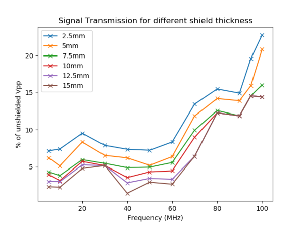
Here, we can see that as the shield material becomes thicker, the amount of shielding provided to the receiver increases, resulting in a lower pick up Vpp. In addition, the data also seems to suggest that the lower frequencies are much easier to shield as compared to higher frequencies. In addition, the shielding efficiency seems to decrease with increasing thickness with some cases having little or no effect on the shielding even when thickness of the shield has increased.
Another property which we can think of is the size (surface area) of the shield. Similarly, we recorded the signal strength in the oscilloscope for a few sizes of the shield to observe the overall effectiveness for various frequencies. For this experiment, we chose to vary only a few different sizes, the smallest one being of comparable dimensions to the emulated emitter and receiver.
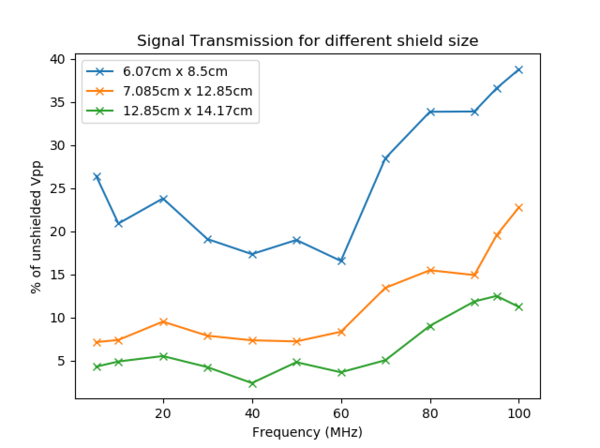
From this plot, we can see that the larger the area, the better the shielding effect. However, the extent of shielding seems to increase much slower as we increase further in size.
Actual RFID Emitter
After testing with a simulated emitter, we then move on to a real life scenario with an actual RFID emitter to test the conditions in which we can shield the actual passive component. To prevent the data from being misused maliciously, we will omit any specific details of the emitter. Firstly, we will look at the emitted signal from the actual emitter with the receiver that was made in the above sections
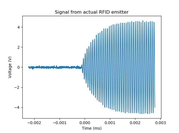
Here, you can see the signal has the frequency at approximately 14.3MHz which is in the RF range as expected.
Next, we see how the emitted signal is influenced when there is a shield plate present. When the shield plate was between the emitter and receiver as shown in the diagram below, there is no signal picked up by the receiver which indicates that the design of the emitter is not a simple one as simulated in the previous section. Further investigations in that aspect could be done to determine why that is the case.
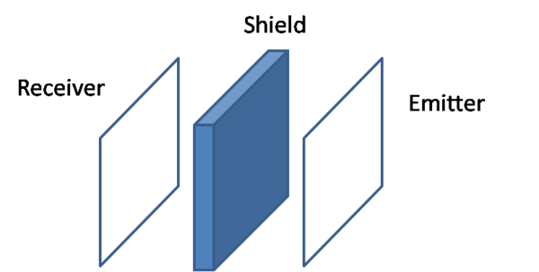
Therefore there is only meaningful information when the receiver is between the shield plate and the emitter as per the diagram below.
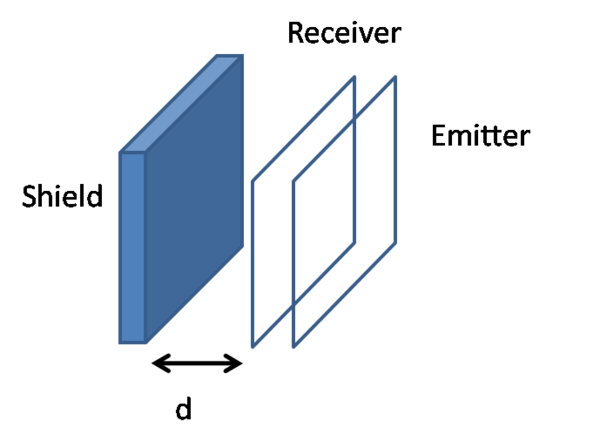
For this experiment, the receiver was kept almost in contact with the emitter while distance of the shield plate to the receiver, d is varied.
We could see that even if the plate is not between the receiver and emitter, the signal picked up is also reduced to some extent, providing a shielding effect for the receiver. For comparison, the actual RFID tag/card for the emitter was found to be functioning only when the shield plate is at least 3mm away from the RFID tag. This could allow to estimate the required Vpp to power the RFID tag which is approximately 8V.
In some cases, there were advice given to not use multiple cards on an emitter. Out of curiosity, we test the receiver along with an actual RFID tag/card meant for the receiver.
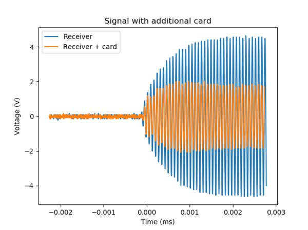
From the data, we can see that there is some attentuation due to the presence of a second card. However, it is not much and in this case, both changes to both 'cards' could have been made which is usually a non ideal outcome.
Comparison of a shielding plate to a Faraday cage
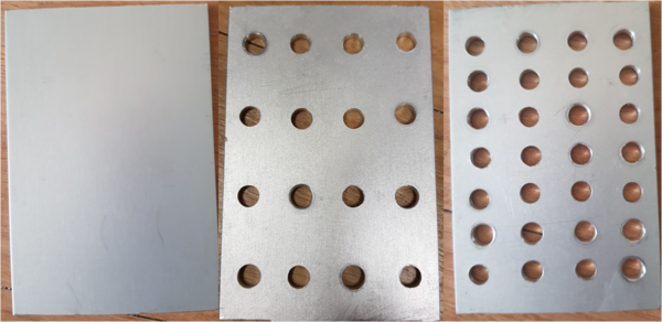
The shielding mechanism works the same way as how Faraday cages work as portrayed in some movies. For a Faraday cage, when an EM field is applied to a conductor, it causes electrons to move within the conductor such that it produces an opposite field that interferes with the incoming EM field. Hence producing a shielding effect. However, this leads to the question of whether or not we need actual material to cover the entire surface of the plate. To put that to the test, holes were drilled into shielding plate to test the quality of shielding after reducing the amount of material in the shield. We compared 3 cases where there were no holes, 16 holes and 28 holes drilled in to the shield. Nevertheless, all 3 plates were able to shield the actual RFID tag from the actual emitter.
Perhaps in the future, more detailed investigation could be performed either experimentally or simulated to investigate various parameters such as:
- Hole density for different frequency
- Shape of holes for different frequency