Argon gas discharge lamp: Difference between revisions
| Line 5: | Line 5: | ||
==Setup== | ==Setup== | ||
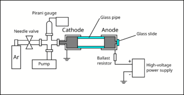
A small air-tight chamber was evacuated with a | A small air-tight chamber was evacuated with a rotary vane pump to about <math>3\times10^{-3}</math> Torr (measured with a Pirani gauge). Then, Argon gas was slowly introduced to the chamber via a needle valve, until the chamber reached the pressure of about <math>10^{-1}</math> to <math>10^0</math> Torr. The metallic cylinder that interfaces with the gas lines forms the cathode of the chamber, and is grounded. Another metallic cylinder (anode) was attached to the cathode using a glass pipe. | ||
[[File:Argon-lamp-schematics.png|360px|Schematics for the Argon gas discharge lamp setup]] | [[File:Argon-lamp-schematics.png|360px|Schematics for the Argon gas discharge lamp setup]] | ||
The glass pipe provides an electrical isolation between the cathode and the anode, and provides a viewport for the experimenter to observe glow discharge. The anode was connected to the positive terminal of a high-voltage power supply, which can reach upto 760 V. Epoxy was used to connect the pieces and seal the vacuum chamber. A ballast resistor (33 kΩ) was added in series with the gas discharge lamp in order to limit the current. The electrodes were mechanically held using laser-cut acrylic plates fixed to an optical breadboard using brackets and bolts. Multimeters were used to monitor the current and the voltage across the lamp. | The glass pipe provides an electrical isolation between the cathode and the anode, and provides a viewport for the experimenter to observe glow discharge. The anode was connected to the positive terminal of a high-voltage power supply, which can reach upto 760 V. Epoxy was used to connect the pieces and seal the vacuum chamber. A ballast resistor (33 kΩ) was added in series with the gas discharge lamp in order to limit the current. The electrodes were mechanically held using laser-cut acrylic plates fixed to an optical breadboard using brackets and bolts. Multimeters were used to monitor the current and the voltage across the lamp. | ||
Additional descriptions about the key components of the setup: | |||
* <b>Electrodes:</b> The electrodes were made by boring a hole through the centre of a cylindrical piece of aluminium(?) using a lathe. | |||
By facing the surfaces and cutting out the corners at 45 degrees angle, sharp edges were minimised to reduce charge leakage through corona discharge. | |||
* <b>Glass pipe:</b> The glass pipe was cut from a longer piece of quartz glass pipe. | |||
* <b>Vacuum fittings:</b> The cathode is connected to a metal pipe attached to a KF blank flange with a hole. The rest of the vacuum fittings are connected via rubber o-rings and clamps. | |||
* <b>High-voltage power supply:</b> | |||
* <b>High-voltage probe:</b> | |||
[[File:Argon-lamp-setup.jpeg|thumb|Argon gas discharge lamp setup]] | [[File:Argon-lamp-setup.jpeg|thumb|Argon gas discharge lamp setup]] | ||
==Measurements== | ==Measurements== | ||
Revision as of 18:12, 27 April 2022
By applying a sufficiently high DC voltage across a gas, the gas atoms/molecules are ionised by the strong electric field. In this project, we construct an Argon-based gas discharge lamp, with adjustable pressure and voltage. The breakdown voltage of Argon gas with respect to pressure changes is observed, and compared with Paschen's law. We also observe changes in the spectroscopic properties of the plasma with varying pressure.
Setup
A small air-tight chamber was evacuated with a rotary vane pump to about Torr (measured with a Pirani gauge). Then, Argon gas was slowly introduced to the chamber via a needle valve, until the chamber reached the pressure of about to Failed to parse (SVG (MathML can be enabled via browser plugin): Invalid response ("Math extension cannot connect to Restbase.") from server "https://wikimedia.org/api/rest_v1/":): {\displaystyle 10^0} Torr. The metallic cylinder that interfaces with the gas lines forms the cathode of the chamber, and is grounded. Another metallic cylinder (anode) was attached to the cathode using a glass pipe.
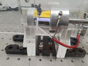
The glass pipe provides an electrical isolation between the cathode and the anode, and provides a viewport for the experimenter to observe glow discharge. The anode was connected to the positive terminal of a high-voltage power supply, which can reach upto 760 V. Epoxy was used to connect the pieces and seal the vacuum chamber. A ballast resistor (33 kΩ) was added in series with the gas discharge lamp in order to limit the current. The electrodes were mechanically held using laser-cut acrylic plates fixed to an optical breadboard using brackets and bolts. Multimeters were used to monitor the current and the voltage across the lamp.
Additional descriptions about the key components of the setup:
- Electrodes: The electrodes were made by boring a hole through the centre of a cylindrical piece of aluminium(?) using a lathe.
By facing the surfaces and cutting out the corners at 45 degrees angle, sharp edges were minimised to reduce charge leakage through corona discharge.
- Glass pipe: The glass pipe was cut from a longer piece of quartz glass pipe.
- Vacuum fittings: The cathode is connected to a metal pipe attached to a KF blank flange with a hole. The rest of the vacuum fittings are connected via rubber o-rings and clamps.
- High-voltage power supply:
- High-voltage probe:
Measurements
The chief advantage of our setup is the capability to adjust the pressure of the Argon gas.
Glow Discharge
We qualitatively observe the changes in the spectroscopic properties in the stable DC Argon plasma, as we vary the pressure. The colours of the glow shifts from pink, to purple, to pale blue, as the pressure increases from approxmiately 0.03 Torr to 3 Torr.
| Pressure (Torr) | Video Frame |
|---|---|
| 0.03 | 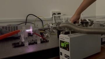
|
| 0.3 | 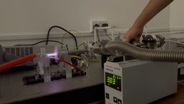
|
| 3 | 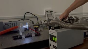
|
File:Argon-lamp-glow-compressed.mp4 (download to view)
Paschen's Law
The ions and free electrons produced from a sufficiently high voltage (above breakdown voltage) move towards the respective electrodes, and current is formed across the lamp. The moving charges collide with other particles to multiply the number of charge carriers in the gas. This process is known as Townsend avalanche or multiplication. The excited atoms and ions decay to the ground state and emit light, in the form of glow discharge.
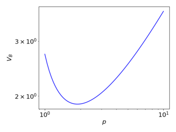
The change in the breakdown voltage with respect to the pressure of the gas can be described by Paschen's Law, according to which the breakdown voltage given by
Failed to parse (SVG (MathML can be enabled via browser plugin): Invalid response ("Math extension cannot connect to Restbase.") from server "https://wikimedia.org/api/rest_v1/":): {\displaystyle V_{\text{B}} = \frac{Bpd}{\ln{(Apd)} - \ln{\Big[\ln{\Big(1 + \frac{1}{\gamma_{\text{se}}}\Big)}\Big]}} }
where Failed to parse (SVG (MathML can be enabled via browser plugin): Invalid response ("Math extension cannot connect to Restbase.") from server "https://wikimedia.org/api/rest_v1/":): {\displaystyle p} is the pressure, Failed to parse (SVG (MathML can be enabled via browser plugin): Invalid response ("Math extension cannot connect to Restbase.") from server "https://wikimedia.org/api/rest_v1/":): {\displaystyle d} is the distance between the electrodes (here, Failed to parse (SVG (MathML can be enabled via browser plugin): Invalid response ("Math extension cannot connect to Restbase.") from server "https://wikimedia.org/api/rest_v1/":): {\displaystyle d} is constant), Failed to parse (SVG (MathML can be enabled via browser plugin): Invalid response ("Math extension cannot connect to Restbase.") from server "https://wikimedia.org/api/rest_v1/":): {\displaystyle \gamma_{\text{se}}} is the secondary-electron-emission coefficient, and Failed to parse (SVG (MathML can be enabled via browser plugin): Invalid response ("Math extension cannot connect to Restbase.") from server "https://wikimedia.org/api/rest_v1/":): {\displaystyle A} and Failed to parse (SVG (MathML can be enabled via browser plugin): Invalid response ("Math extension cannot connect to Restbase.") from server "https://wikimedia.org/api/rest_v1/":): {\displaystyle B} are empirically determined constants. Failed to parse (SVG (MathML can be enabled via browser plugin): Invalid response ("Math extension cannot connect to Restbase.") from server "https://wikimedia.org/api/rest_v1/":): {\displaystyle A} represents the saturation ionisation, and Failed to parse (SVG (MathML can be enabled via browser plugin): Invalid response ("Math extension cannot connect to Restbase.") from server "https://wikimedia.org/api/rest_v1/":): {\displaystyle B} is related to the excitation and ionisation energies.
The above graph illustrates qualitatively how the breakdown voltage varies with pressure, under Paschen's law. When the pressure decreases, the mean free path of the moving charges increases, enabling them to accumulate sufficient energy for the multiplication process with a lower required applied voltage. At the same time however, the collision cross-section also decreases, reducing the occurrence of ionising collisions. At a very low Failed to parse (SVG (MathML can be enabled via browser plugin): Invalid response ("Math extension cannot connect to Restbase.") from server "https://wikimedia.org/api/rest_v1/":): {\displaystyle pd} , the latter effect dominates, and thus a high voltage is needed for the multiplication to begin.


