Schlieren Imaging: Difference between revisions
| Line 32: | Line 32: | ||
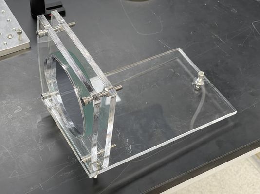
[[File:mirror mount.jpeg|x400px|center|thumb|Fig.Mirror mount]] | [[File:mirror mount.jpeg|x400px|center|thumb|Fig.Mirror mount]] | ||
The huge concave mirror is clamped by two pieces of acrylic frame. The frame is pasted on a plate and there are three screws on the plate | The huge concave mirror is clamped by two pieces of acrylic frame. The frame is pasted on a plate and there are three screws on the plate to adjust the orientation and height of the mirror. | ||
===Version 2=== | ===Version 2=== | ||
Revision as of 12:55, 28 April 2022
Introduction
Schlieren is a method to observe the refractive disturbance of transparent media. It is formally originated by Robert Hooke in the 17th century. At the time it was invented, schlieren was once considered only a qualitative way of visualization. But nowadays, the quantitative usage of schlieren has become widespread in laboratories and industry.
Theory
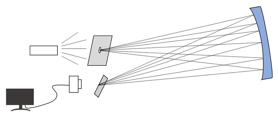
There exist several kinds of schlieren setup. But the basic idea is to convert the refraction index gradient with a knife-edge or pinhole. Here we only give a representative analysis based on our setup shown below.

The light coming out from the pinhole is focused by the concave mirror. The position knife-edge is adjusted so that half of the focused light point is cut off. The light field is then recorded by a camera.
When the beam passes through an area with a refractive index, a small deflection occurs. Therefore, whether the corresponding part of the light field can pass the knife-edge gets changed. Only the deflection orthogonal to the knife-edge needs to be considered, which is written as:
In our experiment, the concave mirror is placed from both the light source and the knife-edge. The sample is placed right before the mirror. So the displacement of light on the knife-edge is . From the angle of Fourier Optics, the knife-edge acts as a spatial filtering component.
Setup
Version 1
The light source is a high-power LED that drives at about 3V 3A. There is an aperture in front of the led to block most of the light and make the source a point source. A concave mirror is located at 2f from the source. The concave mirror has a small angle to the instance beam. So the reflected light will go beside. There is a knife-edge at the reflection path about 2f from the concave mirror. Its function is to block half of the beam. A camera is located behind the knife edge to view the image.
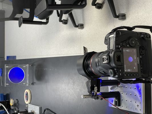
The picture of the real setup looks like below. The concave mirror is on the left hand of the picture while the camera, knife-edge, and the source are on the right-hand side.

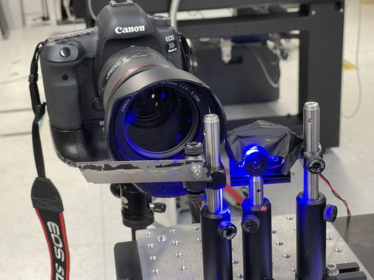
The source and the knife-edge are clearly shown below. A black cover is used to block the stray light so that it will not influence the imaging process as the light from the aperture is relatively too weak. There is a bright blue dot projected on the knife edge. That is half art of the minimum waist radius of the beam. So when the air density changes, the sharp pattern will move up and down and cause the image brighter or darker.

One thing that needs to be careful is not to let the knife-edge/camera be too far from the point source. Otherwise, the smallest wrist will not be round enough. It will come elliptically when the instance beam and the reflected beam are not overlapped very well. The elliptical shape of the beam can harm the resolution of the device.

The huge concave mirror is clamped by two pieces of acrylic frame. The frame is pasted on a plate and there are three screws on the plate to adjust the orientation and height of the mirror.
Version 2
Measurements
....


