A digital oscilloscope Based on MCU: Difference between revisions
Jump to navigation
Jump to search
| Line 11: | Line 11: | ||
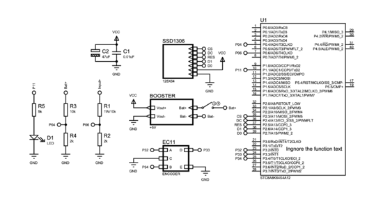
* MCU: STC8A8K64S4A12 | * MCU: STC8A8K64S4A12 | ||
* Display: SSD OLED with 7-Pin SPI Interface | * Display: SSD OLED with 7-Pin SPI Interface | ||
* Resistor:1W 11k | * Resistor:1W 11k&1/4W 2k(for voltage division), 1/4W 11k(for current limiting) ,5k | ||
* Capacitor:47uF, 0.01uF | * Capacitor:47uF, 0.01uF | ||
* EC11 Encoder,Toggle Switch,2-Pin Terminal(for input of | * EC11 Encoder(for controlling of oscilloscope),Toggle Switch(for power switch),2-Pin Terminal(for input of oscilloscope),LED | ||
* IC Socket 40-Pin,Row Pin | * IC Socket 40-Pin,Row Pin(for installation of OLED display and programming the MCU) | ||
* 3.7V Li-ion Battery | * 3.7V Li-ion Battery(power source) | ||
* 5V Booster Module | * 5V Booster Module(power module with Li-ion charging management and boost function) | ||
* USB-TTL Downloader | * USB-TTL Downloader(for downloading program to MCU) | ||
* Circuit Board | * Circuit Board | ||
===Step 2:PCB board design=== | ===Step 2:PCB board design=== | ||
Revision as of 09:05, 29 April 2022
Introduction
We design a digital oscilloscope with STC8A8K64S4A12 chip as the control core, which mainly consists of two modules: hardware circuit and software program. The hardware module mainly includes OLED screen, voltage sampling circuit, clock system, power supply and management module and so on. The software module mainly includes A/D sampling, OLED display, interrupt timing and some necessary data processing. its measurable bandwidth is 0-3000Hz, the measured range is 0-30V. After many tests and comparisons, the design achieves the amplification and reduction of waveform and the measurement of different frequency waveform in the experimental process, so as to achieve the desired goal.
Methodology

Experimental setup
Step 1:Preparation
Material List:
- MCU: STC8A8K64S4A12
- Display: SSD OLED with 7-Pin SPI Interface
- Resistor:1W 11k&1/4W 2k(for voltage division), 1/4W 11k(for current limiting) ,5k
- Capacitor:47uF, 0.01uF
- EC11 Encoder(for controlling of oscilloscope),Toggle Switch(for power switch),2-Pin Terminal(for input of oscilloscope),LED
- IC Socket 40-Pin,Row Pin(for installation of OLED display and programming the MCU)
- 3.7V Li-ion Battery(power source)
- 5V Booster Module(power module with Li-ion charging management and boost function)
- USB-TTL Downloader(for downloading program to MCU)
- Circuit Board