Test
This is the project page of an example project. Start the page with a short description what this is about. The structure below is just a suggestion - use your judgement how you want to present your project. Also, feel free to generate additional pages if this page gets too busy.
Team members
Idea
The aim of the project is to investigate the mechanism behind RFID technology that we may or may not have taken for granted.
Background
Radio-frequency (RF) is a part of the electromagnetic spectrum typically in the range from 10kHz to 300GHz (cite). RF technology is an integral part of our everyday lives. Common examples include phone signals, radio broadcast, ID cards used for various public transport and access control (RFID), various forms of wireless payments including NFCs.
In the case of RFIDs, there is usually an emitter and receiver. The emitter is usually connected to a power source and is constantly emitting a RF signal. This is known as an active component. The receiver on the other hand only has doesnt have a power supply and is usually powered by the RF wave produced by the emitter. It is also known as a passive component. In the receiver, there is also a microchip which stores data which can be extracted and transmitted through these RF waves back to the emitter to trigger certain actions.
Because most of the information transfer happens in the form of an EM wave, it can be transmitted through free space which removes the need for a physical electrical connection between users and hence the term 'Wireless'. However, just like how physical wired connections could be tapped to steal information or to manipulate data stored, such wireless technology is also susceptible to tampering.
To combat this, developments have been made to protect us from such tampering and the solution is to develop shields around the devices that prevent external EM waves from communicating with the device in the case of passive components.
Setup
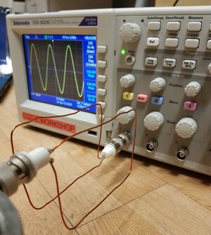
The experimental setup will aim to emulate and emitter and receiver, similar to a typical scenario in RFID systems. On the emitter side, the loop of wire is connected to a function generator (model) while the receiver side is connected to the oscilloscope (model). A gap is left between the emitter and receiver to put in a 'shield' to observe the resulting attentuation on the receiver. In such a setup, the RF waves are generated from the emitter coil and picked up by the receiver coil which is displayed on the oscilloscope. The peak to peak voltage of the signal is taken as a metric to measure the signal strength picked up by the receiver.

Measurements
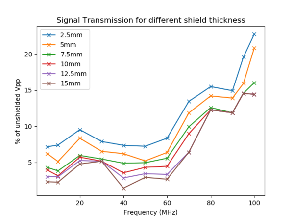
One of the properties that we might think of intuitively when it comes to shielding is the thickness. Here, we vary the thickness a metal plate between both the loops of wire for a range of frequencies available from the function generator.

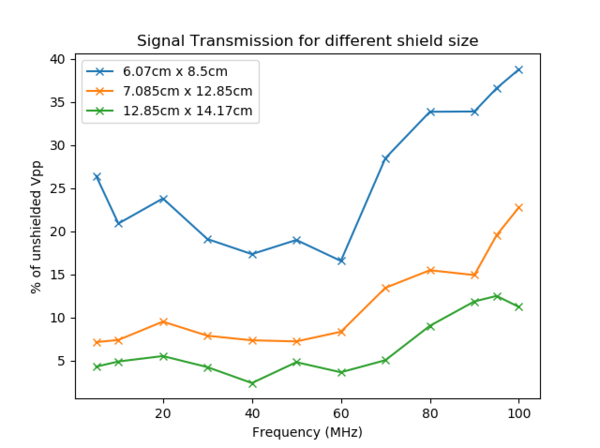
Another property which we can think of is the size (surface area) of the shield. Similarly, we recorded the signal strength in the oscilloscope for a few sizes of the shield to observe the overall effectiveness for various frequencies.
