Anti-glare LCD
1 Team members
Han Shixin(A0236394X)
Ming Xiaohan(A0236400W)
Zhang Yuanyuan(A0236393Y)
2 Idea
Glare is an undesirable lighting phenomenon. To suppress glare, optical films can be used. Based on the electro-optical characteristics of liquid crystals, the project aims to investigate the relationship between voltage and optical characteristics of liquid crystals. At the same time, the orientation and thickness of the liquid crystal are optimized simultaneously to obtain the design parameters of modulable liquid crystal anti-glare film, so that the liquid crystal has high diffraction efficiency at the reflecting end and low diffraction efficiency at the transmitting end.
3 Theoretical foundations
3.1 Introduction
3.1.1 Background and significance of the study
Since birth, humans have relied primarily on vision to obtain information and observe their surroundings. Vision is one of the most important channels through which humans perceive the outside world, and it plays an important role in integrating other sensory tasks such as hearing, smell and touch.
Nowadays, as society is progressing, technology is evolving and mankind has fully entered the digital age. But vision problems, an important part of the visual function, continue to plague people. The complexity of the factors that affects vision, whether genetic or environmental, and the fact that visual impairment at a later stage can exacerbate its decline, have a serious impact on people's quality of life. Not only that, Marques Ana Patricia et al. used population, prevalence and other data to build a model, and after a series of calculations, they concluded that global economic productivity will be affected by people's visual impairment or loss factors, and visual loss in Under certain environmental constraints, the level of poverty will be exacerbated, the quality of life will be reduced, and the employment rate will also be reduced; while formulating effective support policies for the visually impaired, scientific prevention and reduction of vision loss can effectively improve productivity. Glare is one of the factors that can impair visual function later in life.
Glare refers to a visual condition in which people feel uncomfortable in their eyes or react with reduced object visibility due to an uncomfortable distribution of brightness in the normal field of view, or a sharp contrast in brightness in space and time. For example, people often look at their mobile phones in the sunlight, and it is difficult for the operator to see the content of the information on the instrument display under strong sunlight, which is a reflected glare phenomenon, also known as indirect glare; visual discomfort due to the presence of light of excessive intensity in the normal field of vision, such as street lighting decorations of excessive brightness on the roadside or oncoming blinding headlights at night, which is a direct glare phenomenon.

Direct and reflected glare is a widespread phenomenon in our daily lives and is becoming a major concern for society. In the case of direct glare, initiatives are taken in various areas such as traffic and luminaire installation design to avoid the dangers of glare to humans. For the problem of reflected glare, not only scientific measures but also technical support are needed, and anti-glare film is an essential tool to suppress reflected glare. Nowadays, information technology has become a comprehensive part of human life, and a wide range of digital electronics has become one of the most important channels for accessing information. At present, a large proportion of instruments on the market are usually encased in highly transparent glass as the outermost layer near the user's end. When a very bright light source is reflected by the glass to produce a very bright light, or when there is a strong contrast in brightness, the user will feel discomfort due to the reflected glare. Glare not only affects people's visual function and causes inconvenience, but also causes irritability, dizziness, headache, loss of appetite, depression and other symptoms that can cause psychological discomfort and pose a threat to human health and safety. Therefore, the research of anti-glare films is a crucial task and people are paying more and more attention to this field. Based on an in-depth understanding of the principles of glare, researchers have developed and designed a variety of anti-glare films to suppress the generation of reflected glare and reduce its impact on life, and they have been used in various applications such as LCD monitors, vehicle lights and bridge guardrail lights.
The common anti-glare films on the market are made up of tiny particles within the film or rough optical surfaces that cause light scattering, which in turn produces a fogging effect that can effectively suppress glare, and researchers are constantly optimizing the anti-glare film on this basis, but as a passive optical film, this anti-glare film has always had limitations in terms of product application. Because glare does not occur continuously, for example, when looking at a mobile phone or tablet in strong sunlight, but not in dimly lit areas or until nightfall, it is hoped that the anti-glare film applied to the instrument display will become more transparent, allowing more light to pass through from the display so that the information on the display can be obtained more clearly and accurately. The information on the display can be obtained more clearly and accurately. With this in mind, we have designed an electronically controlled anti-glare film that can be applied to the screen of an instrumentation display to add convenience to people's lives.
3.1.2 Glare and anti-glare film
Introduction to glare

Holladay introduced the concept of glare in 1926, believing that it occurred on the cells of the human retina, a term that is now known as disabling glare. In 1928, Stile proposed that glare occurs in the human eye due to media scattering, an idea now known as discomfort glare, and that it can occur in environments with excessive brightness for long periods of time. This is now known as discomfort glare, which is caused by prolonged exposure to an environment of excessive brightness, such as an art gallery or museum with poorly set luminaires, where people may feel uncomfortable or their visual function may be reduced. In addition, adaptive glare is also a common glare phenomenon in life. When the human eye is exposed to drastic changes in the lighting environment, such as coming out of a cinema aisle and walking into the sunlight, it takes time for people to adapt and a brief period of discomfort can occur.
As shown in Figure.2, glare is a common phenomenon in people's lives. In general, disabling glare and adaptive glare are more irritating to people, but they are short-lived and easily noticed, while the phenomenon of discomfort glare formed by reflections from surfaces like instruments and meters, although widespread, is less likely to attract attention, but continuous damage can make people's vision deteriorate and cause harm to human health.

The generation of glare is related to the location and brightness of the light source, as shown in Figure.3. According to the classification of the light source that generates glare, glare can be divided into direct glare and reflected glare.
Direct glare is caused by the presence of bright light sources in the human field of vision, for example, blinding street lights, looking up at the sun, LED displays with too much brightness in busy streets, etc. Reflected glare is caused by the reflection of light from the surface of an object, for example, on shiny metal surfaces with a large reflection coefficient, the sunlight can easily enter the human eye due to its reflection and cause some harm to the human body.
Anti-glare research analysis
As a common optical phenomenon in life, glare has always received close attention from scholars at home and abroad, and researchers have never stopped studying and analysing the problem of glare.
In 1966, Ota. Y and Nonaka.K conducted tests on a new type of contact lens, studied its anti-glare effect and analysed its impact on human visual function. The Institute of Optoelectronic Technology of the Chinese Academy of Sciences has also contributed to the optimisation of the performance of eyeglasses by producing a new eyeglass product with yellow anti-fog, anti-glare and anti-fatigue properties, which is the first gross lens made in China using the drop material one-shot process. Compared to ordinary optical lenses on the market, the effect is remarkable in terms of transparency enhancement. With its anti-fogging and vision-enhancing features, as well as its anti-UV and anti-glare properties, without affecting the clarity of night vision, these lenses have become an ideal tool for car drivers and people working outside in foggy weather. Both the new contact lenses and the new lenses with high performance reflect the fact that researchers have become acutely aware of the dangers of glare on the human body, especially in terms of vision.
At the same time, the level of awareness of the dangers of glare is increasing through ongoing experiments. Thurmon E. Lockhart, Bunji Atsumi and Arka Ghosh recruited 28 participants in university groups and the community to assess the visual acuity of 56 participants by simulating daytime and nighttime conditions, thus investigating the Visual acuity and the relationship between reflected glare and daytime and nighttime driving conditions. Age and distance were found to be two significant influencing factors, with older people responding more significantly under the same glare conditions, and scientific recommendations were made for different age groups. Glare affects not only one's vision but also one's ability to read. Susanne Glimne, Cecilia Österman et al. had 16 subjects perform the same task with normal binocular visual function and controlled variables by controlling the brightness level of direct glare to study the effects of computer work in an experiment based on ensuring that no other glare factors affected. The study showed that light conditions had a significant negative effect on reading ability, and that human control of the binoculars was diminished by direct glare. While the use of electronic devices such as tablet computers can lead to increased visual demands, society cannot progress without digital display technology, and the problem of glare has a real impact on people's access to information as well as on their physical and mental health. Although there has been no clear decree or relevant regulation to explain the management of glare problems, scholars at home and abroad have been exploring means to suppress glare through research in order to create a good visual environment for people and to avoid the hindrance and interference of glare to their normal life.
Anti-glare principles and measures
Different initiatives have been taken in different areas to protect the human body from direct glare.
In terms of architectural lighting, managers pay great attention to the arrangement of lights, indicating that they should limit the brightness and surface area of lamps and lanterns on the principle of concealing the light source and reducing its brightness, while meeting the lighting needs, and stipulating that the installation of lamps and lanterns should take into account glare, ensure a certain protection angle and install the lamps and lanterns as far as possible in places outside the normal range of human vision. Attention should also be paid to the effect of contrast, the higher the contrast, the more likely the glare phenomenon will occur, and by appropriately increasing the background brightness of the light source direct glare can be avoided to cause harm to humans.
Research has also been carried out in the area of automotive lighting and the control of road glare. The polarised headlight system is a solution for the headlights of cars, and designers have also developed asymmetric low beam systems and auto-dimming headlight systems. The asymmetrical near-light system reduces the driver's exposure to direct glare by setting the near-light and the far-light, the polarised headlamp uses a polariser in front of the headlamp to avoid glare due to excessive brightness from the opposite headlamp, and the auto-dimming headlamp suppresses glare by adjusting the light intensity of the headlamp.
The problem of glare interference on motorways is mainly solved by installing continuous anti-glare measures in the central divider of the road, placed at a defined spacing and lateral width to block all or part of the light in front of the vehicle, thus achieving the purpose of anti-glare. In 2021, Yu Jianyou et al. used lighting simulation software to simulate tunnel lighting under different combinations of spacing and angle, with symmetrical distribution of lighting on both sides of the tunnel, in order to analyse the relationship between the angle of incidence of tunnel lighting and the driver's line of sight and the glare phenomenon, and to provide recommendations for optimising the quality of tunnel lighting.
For reflective glare, scientific selection of materials and reasonable arrangement of light sources in daily life are also necessary measures to be taken. In addition to this, anti-glare film is an essential tool for glare problems on various displays and LCDs, mainly by coating the surface of the display to reduce the risk of glare to humans. Scholars at home and abroad have been designing, researching and optimising anti-glare films, and research on anti-glare films has basically been based on changing the structure of the glass surface as a starting point.
3.2 Liquid Crystal
3.2.1 Introduction to liquid crystals
Liquid crystal is a special state of matter between a liquid and a crystal, which has both the fluidity of a liquid and the anisotropy of a crystal, and is known as the "fourth state of matter". In 1888, in the course of an experiment, Reinitzer discovered liquid crystals. As an Austrian botanist, he discovered an interesting phenomenon when conducting experiments on the melting point of certain organic substances: when heating them up, at first the organic substances had a slightly white cloudy, opaque state and would appear in a number of different shades. After heating for some time, the temperature reached a certain value, the white cloudy disappeared and the liquid cleared up and became transparent. At the time, liquid crystals were not well known, but the phenomenon attracted a German physicist - Lehmann. He used a polarizing microscope with its own heating function to further observe this interesting phenomenon and found that these organic substances were birefringent in their opaque state, a special property of crystals. Based on the special properties of this substance, Lehmann gave it the name "Liquid Crystal". After liquid crystals were officially named, a number of interested scientists explored them further, but the experimental environment and knowledge were limited to theoretical research, and no breakthroughs were made at the application level. As society moved forward and industrialization reached a certain level, liquid crystals came to the fore.
3.2.2 Classification of liquid crystals
The classification criteria are different and the classification results for liquid crystals will be different. Liquid crystals can be classified as thermogenic liquid crystals or solvogenic liquid crystals, based on the conditions of formation of the liquid crystal state. Thermogenic liquid crystals are liquid crystals where the liquid crystal state exists within a certain temperature range, and solvogenic liquid crystals are liquid crystals where the liquid crystal state exists within a certain concentration range. There are also different results according to the classification of the molecular geometry of liquid crystals. The classification of liquid crystals differs according to the arrangement of the molecules and can be divided into the Nematic phase, Semiotic phase, and Chelesteric phase. The molecular arrangement of nematic phase liquid crystals is one-dimensional and ordered, but the center of gravity of the molecules is disordered. Unlike the nematic phase liquid crystals, the molecules of the proximal phase liquid crystals are all arranged in layers. The molecules in each layer of the near-crystalline A phase are arranged in one dimension and are ordered, but the center of gravity of the molecules is disordered; the molecules in each layer of the near-crystalline B phase are also arranged in one dimension and are ordered, and the center of gravity of the molecules are ordered; the molecules in the near-crystalline C phase are arranged in one dimension and are ordered, and the center of gravity of the molecules is disordered, but there is an angle between the arrangement of the molecules in the layer and the layer normal. The molecules of cholesteric liquid crystals are helically arranged, and on the surface perpendicular to the cross-section of the helical axis, the liquid crystal molecules are arranged in one dimension and are ordered, but the center of gravity of the molecules is disordered.
3.2.3 Several important parameters of liquid crystals
The pointing vector of a liquid crystal is the direction in which the liquid crystal molecules point and is the most fundamental element in the study of liquid crystal topics. The pointing vector is generally denoted by "n". It is an idealized statistical physical quantity that describes the average pointing direction of a liquid crystal molecule, has no dimension, and is a unit vector. The order parameter, i.e., the orientation order parameter of the liquid crystal, is denoted as "S". When S=0, the system is in a disordered state; when S=1, the system is in a completely ordered state. The order parameter of the liquid crystal is between 0 and 1 (excluding 0 and 1).

3.2.4 Liquid crystal orientation technology
Liquid crystal orientation technology is the key to the preparation of liquid crystal instruments. The technology has been widely used for over a century, from 1911 to the present. The frictional orientation technique uses a material such as cotton lint or nylon, which is set in the direction of the frictional orientation and then rubbed against the orientation layer to give it a certain shape. Due to the anchoring effect of the orientation film, the molecules around the orientation layer will cause the liquid crystal layer molecules to show a certain regular arrangement, thus achieving the purpose of orientation. There are two theories of this technology: the "groove" theory and the "orientation of molecular chains on the surface of the oriented layer" theory. Groove theory refers to the higher density of grooves created by friction. From the point of view of low energy and high system stability, the liquid crystal molecules are aligned along the grooves and the intermolecular interactions result in a stable arrangement of the oriented layers.

The theory of "surface molecular chain orientation" refers to the action between the liquid crystal molecules and the orientation layer. When the orientation layer is rubbed, special molecular chains emerge, which are extended when the molecules come into contact with it, and then extend to form a specific orientation. At present, neither of these two theories provides a perfect explanation of the mechanism of frictional orientation, and this method of contact orientation has a long history, but still requires further research. Later on, some non-contact orientation techniques emerged: ion beam orientation, oblique vapour deposition, light orientation techniques, etc.. One of these technologies, photo-orientation, refers to the physical or chemical reaction that occurs when light is directed into a material, due to its photosensitive properties, thus causing the liquid crystal molecules to achieve a specific pointing. Light-controlled orientation is widely used because it avoids static electricity, dust and other contamination and can be used to make multi-domain devices.
4 Experiment
4.1 Current luminous flux characteristic of the liquid crystal
4.1.1 Instruments
Laser source, liquid crystal box, light intensity detector, digital multimeter, functional signal generator, optical experimental table
4.1.2 Measurement

The construction of the optical path should be based on the principle of optical experiments as shown in figure. Keep laser source, liquid crystal and light intensity detector on the same height and line. Digital multimeter is used to measure the voltage which will be converted to the light intensity by a certain relation. We use the functional signal generator to apply a square signal on the liquid crystal box.
By changing the output voltage of the functional signal generator, the orientation of the liquid crystal change from 0° to 180°. The laser goes through the liquid crystal and is collected by the detector. Note down the voltage shown on the multimeter’s screen under different output voltages of signal generator and convert it into light intensity. The converting relation is:


4.1.3 Measurement results
Plot the light intensity by the voltage applied on the liquid crystal, we will learn the current luminous flux characteristic of the liquid crystal.

According to the graph, the transmissivity of the liquid crystal drops in the voltage range of around 1V~2V, which means the orientation of the liquid crystal varies significantly during this range. We can observe this phenomenon by the Matlab simulation as following.
4.2 Programming
Due to the limitations of the actual experiment, we used programming to expand and supplement the topic.The programming was carried out using MATLAB software for simulation. MATLAB is a mathematical application that uses matrices as the basic unit of data, but is not limited to purely mathematical matrix operations, data analysis, image processing and other functions, but is used in various fields.
4.2.1 Design
This design is studied with liquid crystal material, which has unique properties as a special substance between crystals and liquids. On the one hand, liquid crystals have the fluidity of liquids, and on the other hand, liquid crystals have the unique anisotropy possessed by crystals, including optical anisotropy and electrical anisotropy. Optical anisotropy (n) refers to the difference in refractive index exhibited by liquid crystals in the direction pointing toward the loss versus perpendicular to the direction pointing toward the loss, and electrical anisotropy (ɛ) refers to the difference in dielectric constant embodied by liquid crystal molecules in the direction parallel to the direction pointing toward the loss versus perpendicular to the direction pointing toward the loss. As uniaxial crystals, liquid crystal molecules have birefringent properties, which can be graphically described by the refractive index ellipsoid in the following figure. The Z-axis is the direction of the optical axis, no is the refractive index of unusual light, ne is the refractive index of unusual light, and their magnitudes can be expressed by the lengths of the corresponding line segments on the refractive index ellipsoid. If we set the lengths along the X and Y axes as n⊥ and along the Z axis as n∥, and the K-axis direction as the incident light incidence direction. The innovation point of this design is based on the characteristic of liquid crystal which can be regulated by electric field, that is, the photoelectric property of liquid crystal. When liquid crystal molecules are arranged in an orderly manner, they will show anisotropy. By applying a certain voltage to the liquid crystal box, the orientation of the liquid crystal layer molecules can be changed, thus the optical properties of the liquid crystal box also change, which is a rare characteristic of other materials and an important reason why liquid crystal materials are widely used. There are already many liquid crystal devices that are widely used, taking the optical switch model as an example. Twisted nematic liquid crystal (TN) has a special property that when polarized light is incident from the upper substrate through the liquid crystal layer to reach the lower substrate, the polarization direction of the light will be 90 degrees different from the original polarization direction, i.e., perpendicular to the original polarization direction. As shown in the Figure 8, the polarizer P1 and polarizer P2 are placed orthogonally, and the incident natural light becomes polarized light through the polarizer P1, and after the twisted liquid crystal layer, the polarization direction is rotated by 90 degrees, and the polarizer P2 transmits light in the same direction, so that the light can pass through smoothly. The basic framework for programming this program is shown in Figure 9.
-
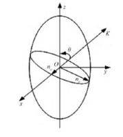 Figure 7.Refractive index ellipsoid diagram
 -
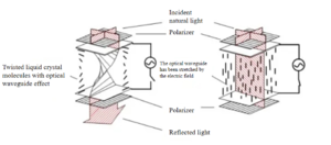 Figure 8.Twisted Nematic Type (TN) LCD Optical Switch Schematic
 -
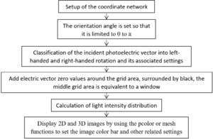 Figure 9. Programing diagram

_LCD_Optical_Switch_Schematic.png)

4.2.2 Results
Testing of procedures
Assuming that the plane in which the liquid crystal device is located is the X-Y plane and the direction of the grating period is along the X-axis, the azimuth of the liquid crystal molecules ∅ within a grating period has the following relationship:

C is a constant and is the grating period; x refers to the spatial position in which the liquid crystal molecule is located during a period.
The expression for the transmittance matrix T of a liquid crystal polarization grid is:

The rotation matrix R(θ) is:

In general, liquid crystals absorb and scatter light. Without considering this phenomenon, A = 1, B = exp(iδ), δ, also known as the kinetic phase, is substituted into T to obtain:

Analysis of the transmittance matrix T shows that the outgoing light will have 3 levels: -1, 0 and +1. Level 0 diffracted light is the beam that keeps its incident light in the direction of incidence. From geometric phase theory, it is known that e^i2∅ and e^-i2∅ are the additional geometric phases after passing through the geometric phase device. The matrix expression for left-handed circularly polarised light is:

Assuming that the beam is left-rotating circularly polarised light, the outgoing field after passing through the liquid crystal device is Eout, Eout =T* Ei, the transmittance in this case is:

At this time, the outgoing light has two diffraction levels: -1 level and 0 level; 0 level outgoing light is the same as the incident light polarization state, for left-rotating circularly polarized light; -1 level diffracted light is right-rotating circularly polarized light; the phase is π, that is, when the liquid crystal device meets the half-wave condition, it is a special point, at this time the outgoing light is only -1 level this level.
After completing the program design, the program is checked by entering special values for which the results are known. From the above theory, it is known that in the operation of this program design, when the phase difference is π and the azimuth of the liquid crystal molecule satisfies the following expression.

If there is only one diffraction level for left and one for right circularly polarised light, then a total of two diffraction levels can be observed on the receiving screen. After filling in the relevant parameters in the corresponding positions, the resulting graph is shown below.
-
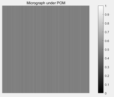
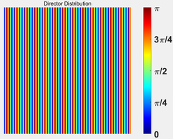 Figure 10. Liquid crystal molecule pointing vector distribution map and grayscale map under polarized light microscope
 -


-
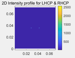 Figure 11. Two-dimensional light intensity distribution and its stereogram
 -
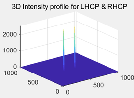


As can be seen from the figure, the light intensity distribution received on the diffraction screen after the incident light has passed through the polarisation grating, only the light intensity at the two diffraction points has a value of non-zero, while the light intensity in all other regions is zero, which means that the diffracted light has only two diffraction levels. To further investigate and analyse the diffraction situation, the light intensity distributions of the left- and right-hand circularly polarised light are enlarged separately as follows.
-
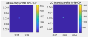 Figure 12. Light intensity distribution of left-rotating circularly polarized light and right-rotating circularly polarized light

The number of diffraction levels for both left- and right-handed circularly polarised light can be seen visually in the enlarged diagram, both of which have only one diffraction level, in good agreement with the results derived from the theory.
Parameter optimisation and analysis process
The box thickness (d) and the orientation of the liquid crystal layer are two factors that influence the effect of light dispersion from the emitted light. With one of these factors determined, the other variable can be further optimised to find the optimal parameter. The relationship between box thickness (d) and diffraction efficiency can be expressed by the following equation.

The phase difference satisfies:

In general, the∆ n is taken to be between 0.1 and 0.2 and the laboratory achievable liquid crystal cassette thickness (d) is between 0.6875 μm and 1.375 μm. The relationship between box thickness and diffraction efficiency can be analysed by taking m = 1 for a certain number of other variables in the control equation then.

The effect of box thickness on the effect of light dispersion is achieved by affecting the diffraction efficiency. As mentioned earlier, we want the diffraction efficiency of the reflected light from the glass surface to be as large as possible and the diffraction efficiency of the transmitted light with valid information from inside the instrument, such as the display, to be as small as possible. From the diffraction efficiency formula without considering the transmitted light inside the instrument, when the phase difference "δ" is π, the sine function on the denominator in the diffraction efficiency equation can be taken to a maximum value of 1. At this point, the diffraction efficiency can reach its maximum value, but the influence of the background light transmission inside the instrument has to be considered, so the box thickness (d) parameter has to be further optimized in detail. For reflected light, the incident light is reflected out through the anti-glare film once more after it has passed through the anti-glare film and reached the surface of the instrument, whereas for transmitted light it will only pass through the anti-glare film once. The phase difference in this experimental design is based on reflected light, meaning that the amount of phase delay after the reflected light passes through the liquid crystal device is twice as much as the amount of phase delay after the transmitted light exits at the same box thickness. As can be seen from the diffraction efficiency formula, the square of the sine function has a period of π. Therefore, the box thickness is continuously optimized by calculating and analyzing the diffraction efficiency of the reflected and transmitted light using various parameters of the liquid crystal, with the reflected light phase difference lying between 0 and π. Using the TEB300 liquid crystal as an example (∆ n=0.163), the incident light is green, and the corresponding phase difference is calculated over the range of box thicknesses (0.6875 μm-1.375 μm) to obtain the diffraction efficiency. The diffraction efficiencies of reflected and transmitted light for different box thicknesses are as follows.

Once the parameter of phase difference has been determined, the orientation parameters of the liquid crystal can be optimised in relation to it. Firstly, the design uses a common two-dimensional grating structure such that the orientation angle α(alpha) of the liquid crystal molecules satisfies. alpha=mod(pi.*Xo/device_para,pi/2) The results of running the program are as follows.
-
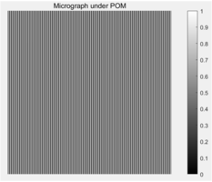 Figure 13. Grayscale images under polarized light microscope.png
 -
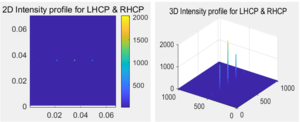 Figure 14. Image of intensity distribution of 2D grating light (left- 2D image, right- stereo image)

.png)
The distribution of the light intensity can be clearly seen from the above picture, the higher the diffraction level, the weaker the light intensity. However, the variance in this case is calculated to be 16.0027 and it can be seen from the 3D stereogram that the diffracted light shows a one-dimensional distribution and does not show a better scattering effect. On the basis of the already determined box thickness parameters, in order to achieve a better scattering of the emitted light, this design uses the rand function for the binary phase element to set the orientation angle of the liquid crystal molecules: floor(rand(2,2)/0.501)*(pi/2), so that the pointing angle of the liquid crystal molecules is randomly taken as 0 or pi/2, so as to achieve the orientation of the liquid crystal molecules in the region The random distribution of liquid crystal molecules in the region is achieved. In this case, the relationship between the number of pixels selected and the effect of light dispersion is further investigated by simulation. The initial attempt at a pixel point selection of 4 x 4 resulted in the following program run.
-
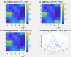 Figure 15. Light intensity distribution in the case of 4×4 pixel point selection
As can be seen from the figure, the two-dimensional image of the light intensity distribution appears mosaic, and the stereo image is too rough and not detailed, the image does not have reference value. The reason for this is that the Fourier transform operation in the program requires a 512 x 512 pixel map, but the current sampling number is only 4 x 4, which is less than the number of pixels needed for the Fourier transform. To solve the above problem, the program uses the imresize function to uniformly convert the image of any pixel selection number into a picture of 512×512 size without distortion, and by observing the liquid crystal pointing vector distribution and light intensity distribution in different cases, the connection between the pixel selection number and light scattering effect is analyzed in depth. With the optimal box thickness value of 0.8267 μm, controlling all other variables constant and the number of pixels chosen to be 4 x 4, the program runs as follows.
-
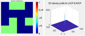 Figure 16. Light intensity distribution in the case of 4×4 pixel point selection
As can be seen from the diagram, when the number of pixels is 4 x 4, the liquid crystal pointing vector map shows 16 blocks of colours without distortion; however, in this case, the spatial distribution of diffracted light is basically concentrated in the middle point and does not show any scattering. The next study was carried out for the case where the number of pixel points selected was 8 x 8 and the program was run as follows.
-
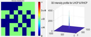 Figure 16. The result of running the program when the element is selected as 8×8

At this point, a 64-grid colour block is presented in the pointing loss distribution, and visual observation of the light intensity distribution shows that the diffracted light intensity still does not show a spread, but there is a tendency for the light to spread from one point to the surrounding area compared to the case where the pixel points are selected as 4 x 4. Next, the number of pixel points selected is studied for 16 x 16, 32 x 32, 64 x 64, 128 x 128, 256 x 256 and 512 x 512 respectively.
-
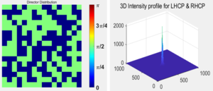 Figure 17. The result of running the program when the element is selected as 16×16
 -
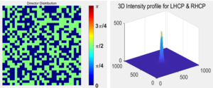 Figure 18. The result of running the program when the element is selected as 32×32
 -
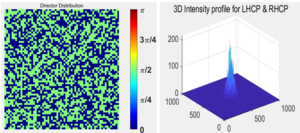 Figure 19. The result of running the program when the element is selected as 64×64
 -
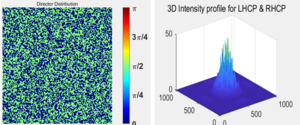 Figure 20. The result of running the program when the element is selected as 128×128
 -
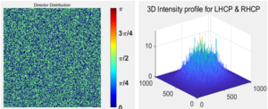 Figure 21. The result of running the program when the element is selected as 256×256
 -
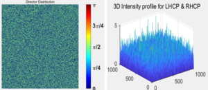 Figure 22. The result of running the program when the element is selected as 512×512


Comparing the above pictures, we can see that as the number of pixel points increases, the number of colour blocks in the liquid crystal pointing vector distribution map becomes more and more, and the more uniform the distribution of liquid crystal molecules pointing vectors in the region; at the same time, visually and intuitively, the diffracted light intensity distribution increases with the number of pixel points, from concentrating on one point to the surrounding distribution, and when the pixel points are selected as 512×512, the effect of light scattering is The best. Unlike the usual two-dimensional grating, the liquid crystal orientation angle can be set randomly to produce a micro-zone orientation structure similar to a two-dimensional code pattern, i.e. a random grating structure, which will cause light to propagate in all directions, achieving the purpose of anti-glare. In order to more accurately and scientifically describe the relationship between the number of pixel selection points and the light dispersion effect, and further study and analyse the stability of random orientation, on the basis of the existing program, the design uses the std2 function to process the mean square difference of the light intensity magnitude at each point each time the program is run. The greater the mean squared difference, the greater the light intensity at some diffraction level, and the smaller the mean squared difference, the better the light dispersion. The mean squared deviation values were A, B, C, D, E, F, G, H and I for 4 x 4, 8 x 8, 16 x 16, 32 x 32, 64 x 64, 128 x 128, 256 x 256, 512 x 512 and 1024 x 1024 pixel points, respectively, and the results were repeated 15 times for each case as follows.
-
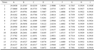 Figure 23. Mean Square Error Statistics Table

As can be seen from the data in the graph, as the number of pixel points selected increases, the value of the mean squared deviation of the light intensity becomes progressively smaller, indicating that the scattering effect is getting better and better, in line with the results obtained from visual observation of the stereogram of the light intensity distribution of the emitted light. In addition, it can be observed that the more the number of pixel dots, the more stable the light scattering effect of the 15 runs with that number of dots, i.e. the more uniform the liquid crystal tends to point in the wrong direction; in particular, the mean squared difference value does not change when the number of dots is 512 x 512 and 1024 x 1024, indicating that when the number of dots reaches a certain level, the randomness of the orientation angle of the liquid crystal molecules no longer have an effect on the light scattering effect. At this point, it is no longer meaningful to increase the number of selected pixels, and the system maintains the highest level of light dispersion, achieving a stable anti-glare effect. In order to verify more visually whether the scattering of the number of pixels 512 x 512 and 1024 x 1024 matches the results of the mean squared deviation calculations, the design intercepts the stereogram of the light intensity distribution in both cases for comparison.
-
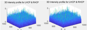 Figure 24. Pixel point selection for 512 × 512 and 1024 × 1024 light intensity distribution comparison chart
As can be seen from the light intensity distribution shown in the graph, good light dispersion is achieved in both cases. Based on the determination of the relationship between the number of pixel points selected and the effect of light dispersion, the parameter of box thickness can be further verified. For the TEB300 liquid crystal, the box thickness ranges from 0.6917 μm to 0.8436 μm. Therefore, with the optimal value of the liquid crystal box orientation parameter, the effect of different box thickness values on the light intensity distribution was further verified by simulating the mean squared deviation as follows.
-
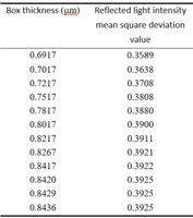 Figure 25. Mean squared deviation values for different box thickness values

As can be seen from the data in the table, the mean squared deviation of the light intensity distribution becomes larger as the box thickness increases, and the mean squared deviation of the reflected light intensity distribution basically remains the same when the box thickness is between 0.8267 μm and 0.8436 μm, i.e. the reflected light phase delay tends to π. This indicates that the reflected light diffraction efficiency also remains basically the same at this time, which is consistent with the curve of reflected light diffraction efficiency with box thickness in Figure 3-14 and Figure 3-15. This is consistent with the variation of the reflected light diffraction efficiency with box thickness in Figures 3-14 and 3-15. In summary, when the box thickness of the TEB300 liquid crystal is 0.8267 μm and the molecular orientation of the liquid crystal is randomly distributed to meet the number of pixels selected as 512 x 512, the light emitted can achieve a good scattering effect.
5 Conclusion
5.1 Conclusion and future prospect
Conclusions
Glare is an optical phenomenon that researchers have been trying to solve. In view of the common phenomenon of glare on the glass surfaces of instruments and other instruments in daily life, which is harmful to human visual functions, this work proposes the use of liquid crystal materials as the material selection for the preparation of anti-glare films. The purpose of this work is to make up for the fact that the existing anti-glare films in the market cannot respond to the light environment in a timely manner. Liquid crystals are a state of matter between a liquid and a crystal, which has both the fluidity of a liquid and the anisotropy of a crystal and can respond to electric fields. Liquid crystal materials have been widely used in various fields and have a bright panorama. In this work, based on the experiment analysis and the analysis of liquid crystal properties, the MATLAB software is used to design a program to simulate the light path model to reduce the light entering the human eye by making the outgoing light as scattered as possible, thus achieving anti-glare purposes. The box thickness affects the light scattering effect by influencing the diffraction efficiency, while the pointing of the liquid crystal layer directly affects the light scattering effect. For the optimization of the box thickness, the diffraction efficiency for different box thicknesses is calculated by the diffraction formula and the corresponding graphs are made using origin software. Based on this, the design was optimized for the liquid crystal layer orientation parameter. In general, two-dimensional gratings do not disperse light in space, but show a one-dimensional distribution, so the design idea takes the form of a random grating, for the binary phase element, so that the liquid crystal molecules are oriented at a random angle of 0 or π/2. If the number of pixels is increased, the light distribution does not change significantly and reaches a stable state. The design is based on the principle of light scattering and the selection of liquid crystal as a special material, which is a complement to the existing types of anti-glare film on the market and provides an innovative idea for anti-glare means, and also lays the foundation for further optimization research on the performance of subsequent anti-glare films.
Future prospect
The design uses MATLAB software to simulate the light path model, find the appropriate box thickness parameters and determine the orientation of the liquid crystal layer molecules that can achieve a better light dispersion effect, laying a good foundation for the realization of the anti-glare film. In practical applications, the corresponding box thickness parameters need to be determined according to the specific characteristics of the liquid crystal being taken. Under different light patterns, scientific adjustments have to be made according to the specific situation. However, this innovative design attempt offers the possibility of achieving a stage breakthrough in the performance of the anti-glare film. Based on this design idea, the design procedure can be considered to achieve a wide band response, and this optimization process lays a solid foundation for subsequent practical applications. With the rapid development of the market, DMD maskless lithography has been widely used in various fields. In the problem of orientation of liquid crystal layers, the use of DMD machine can realize the patterned orientation and zonal orientation of liquid crystal molecules. This design can achieve the output of the target orientation picture by writing the program, using DMD maskless lithography machine can achieve the orientation of the liquid crystal layer molecules, put the design scheme into practice, also contribute to the progress of anti-glare technology.
5.2 The basic principles and methods of optical system construction
Based on the process of optical path construction in this design, some basic principles and methods of optical path construction and adjustment with universality are summarized here.
5.2.1 ‘Orderly step-by-step’ principle
The entire optical system can be broken down into many sub-targets, and the order of sub-targets has a definite direction and is unidirectional. On this basis, the entire optical system construction and commissioning process is decomposed into a step or link. The completion of the former step is the basis for the latter step, and the realization of the latter step depends on the result of the former step. The failure of the previous step, or the poor quality of its completion, will lead to the degradation of the quality of the latter step, the increase of the difficulty of debugging, and even the failure. It is difficult for the latter step to effectively correct the deviation of the former step. The later step should not affect and destroy the result of the previous step.
5.2.2 Criteria for dividing steps
The delineated steps should be ‘single’ and ‘independent’. ‘Unity’ means that each step is divided into a single debugging goal to be achieved. If a step contains multiple debugging goals, they should be uncoupled and independent of each other. ‘Independence’ means that the operation of each step should be limited to the equipment and devices associated with that step and not involve the operation of equipment and devices in other steps. Of course, because the complexity of optical systems vary, the structure and function of equipment and devices vary, and it is not always possible to make each step absolutely satisfy the criteria of ‘unity’ and ‘independence’. However, the steps should still be classified as close to this criterion as possible.
5.2.3 Regulation with a defined beam path

The beam is adjusted from its original path to the given path, given the path through which the beam has to pass. The way the beam path is given is usually by using two scales, such as diaphragms, where the line at the center of the diaphragm uniquely defines the beam path. During the adjustment process, the diaphragms are not moved, but rather the position (and height) of the light source is adjusted by translation and the angle of the light source is adjusted by rotation so that the beam from the light source can pass through the centers of both diaphragms at the same time. This operation is not only used in the light path construction, but also useful in the light path recovery. A common case where the beam path has been set is a parallel/horizontal path. In this case, it is also possible to use only one diaphragm and place it as far and as near as needed in the adjustment process, so that both diaphragms can serve the same purpose. Figure.26 illustrates the adjustment procedure in this way. First, the diaphragm is placed close to the light source, and the height and position of the light source are adjusted in translation so that the beam passes through the center of the diaphragm, as shown in step (a) in Figure 4-1; then the diaphragm is placed far away along the path, and the angle of the light source is adjusted in rotation so that the beam passes through the center of the diaphragm again, as shown in step (b); (c) when the diaphragm is again close to the light source and the beam is deflected from the near diaphragm, the light source is adjusted in translation position and height, so that it passes through the center of the near diaphragm; (d) then put the diaphragm at a distant position, turn the angle of the adjustable light source, so that the beam passes through the center of the diaphragm; repeatedly carry out the operation of (c) and (d) until when the diaphragm in the near and far position, both can be passed by the beam from the center as shown in figure (e), the adjustment of horizontal/parallel is completed. If you use two diaphragms, the operation principle is the same, based on the proximal diaphragm to pan to adjust the light source position and height, based on the distal diaphragm rotation to adjust the angle of the light source.