Kerr Microscope: Difference between revisions
| Line 29: | Line 29: | ||
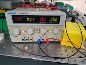
[[File:MOKE power supply.jpeg|thumb|Power supply for LED]] | [[File:MOKE power supply.jpeg|thumb|Power supply for LED]] | ||
We only used the two knobs on the right hand side. First turn the voltage up slightly to set a limiting voltage, then slowly turn on the current till the LED turns on. Observation shows LED tends to turn on at about 2V. The positive end (red) should be connected to the positive (anode) side of the LED. This can be seen as the longer leg of the LED. | |||
===15 Feb 2022=== | ===15 Feb 2022=== | ||
Revision as of 12:17, 28 February 2022
Imaging a sample can be done in many ways, depending on the light-matter interaction we are interested in observing. The magneto-optic Kerr effect describes the change in polarization and intensity of incident light when it impinges on the surface of a magnetic material. The resultant reflected light can then form an image through focusing optics which provides high contrast between areas of different magnetization.
Through Kerr microscopy, we aim to characterize the relative changes in magnetization across a magnetic sample.
Team members
- Joel Yeo
- Gan Jun Herng
(Feel free to edit this page or email me at joelyeo@u.nus.edu if you would like to join.)
Idea
In this project, we will be aiming to build a basic Kerr microscope using off-the-shelf polarizers, objectives, detectors and laser source. A magnetic sample can be borrowed from a team member's research lab. To increase the field of view, we also plan to incorporate automatic raster scanning of the sample through means of an Arduino-controlled sample stage.
Some useful search keywords are:
- Faraday rotation
Setup
Location: S11-02-04
Lab Session Logs
10 Feb 2022
Hunted down the required parts. We used the diagram from NaBiS from Politechnico di Milano’s physics department as our guide.
Linear polarizer was found, but extremely dirty. First rinsed with water than finished cleaning with isopropanol (IPA). IPA available in S11-02-04 room cupboard. Discussed some other things between us and with TAs:
- Stage requires mm precision
- blah

We only used the two knobs on the right hand side. First turn the voltage up slightly to set a limiting voltage, then slowly turn on the current till the LED turns on. Observation shows LED tends to turn on at about 2V. The positive end (red) should be connected to the positive (anode) side of the LED. This can be seen as the longer leg of the LED.
15 Feb 2022
From the info on the NaBiS page, we may need to characterise the material in all three MOKE orientations to get a full 3D image. But we’ll think about that later.
Today was more parts gathering, a little machining to make the parts that we need.
Magnetic material - Got a bunch of steel sheets from CK, and some copper wire to wrap around it like a mini solenoid. The sheets are a soft magnetic material ( = 5000 − 7000 according to CK) and will be magnetised when a current runs through. CK suggested we set it up so we can change the direction of the magnetic field by switching ??? (not exactly sure, will need to figure out later), and not manually moving the sample. Might be easier down the road.
The steel sheet was cut with some steel cutting scissors, and de-burred with sandpaper. The copper wires had to be stripped for connection. This was done with some Stanley blades and polished with some sandpaper. Not the cleanest, but as long as we get a current it’s fine.
