Custom atomic beam source: Difference between revisions
| Line 102: | Line 102: | ||
= Conclusion = | = Conclusion = | ||
= Reference = | |||
Revision as of 01:46, 13 April 2022
Team Members and Lab location
Lu Tiangao, Li Putian in S14-03 Travis's Lab
Introduction
In this report, we introduced an atomic oven designed by ourselves. The whole design will be suitable for atoms that need temperature ranging from 500K to 1300K. The idea came from our lab's commercial atomic beam source was both expensive and having some defects.
Theory part
Vapor Pressure
Indium is the group III atom, and it has two stable isotopes In-113 and In-115, the atom we use is In-115 with an abundance of 95.7%, the melting point is 156.6°C. To calculate the density of atoms coming from the nozzles. We should know the pressure and temperature of the gas, which the density formula is given by:
Failed to parse (SVG (MathML can be enabled via browser plugin): Invalid response ("Math extension cannot connect to Restbase.") from server "https://wikimedia.org/api/rest_v1/":): {\displaystyle \begin{alignat}{2} \rho(T)=\frac{p(T)}{k_{B}T} \end{alignat} }
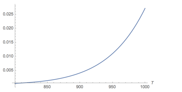
When a material is in thermodynamic equilibrium with its vapor at a given temperature in a closed system, the pressure at this time is called vapor pressure. The vapor pressure of indium is given by
Failed to parse (SVG (MathML can be enabled via browser plugin): Invalid response ("Math extension cannot connect to Restbase.") from server "https://wikimedia.org/api/rest_v1/":): {\displaystyle \begin{alignat}{2} \lg\frac{p}{Torr}=8.003-\frac{12180}{T+273.15} \end{alignat} }
We can plot the vapor pressure with Temperature range from 800°C to 1000°C:

A pressure of 1e-3 torr is a number typically used in many cold atom experiments. Thus we get the temperature around 833.82°C is the suitable temperature of indium atom experiment. Then, according to the density formula, we can get the density of atoms inside the crucible is Failed to parse (SVG (MathML can be enabled via browser plugin): Invalid response ("Math extension cannot connect to Restbase.") from server "https://wikimedia.org/api/rest_v1/":): {\displaystyle \begin{alignat}{2} \rho(T)=\frac{p(T)}{k_{B}T} = \frac{10^{-3}*133}{(833.82+273.15)*1.3806^{-23}} = 8.73*10^{18}m^{-3} \end{alignat} }
Maxwell distribution
Firstly, indium atoms inside the crucible will obey the Maxwell-Boltzmann distribution.
Failed to parse (SVG (MathML can be enabled via browser plugin): Invalid response ("Math extension cannot connect to Restbase.") from server "https://wikimedia.org/api/rest_v1/":): {\displaystyle \begin{alignat}{2} f_{MB}(v)dv=\sqrt{\frac{2}{\pi}}\frac{v^2dv}{\sqrt{k_B T/m}^3}e^{-mv^2/{2k_B T}} \end{alignat} }
However, when considering the speed distribution of the atoms coming out of the nozzle, we should add another factor of v into the distribution function. Because the gas atoms emerging outside of the small apertures cannot be representative of the atoms inside the crucible. So the distribution function of the outside atoms is given by:
Failed to parse (SVG (MathML can be enabled via browser plugin): Invalid response ("Math extension cannot connect to Restbase.") from server "https://wikimedia.org/api/rest_v1/":): {\displaystyle \begin{alignat}{2} f(v)dv={\frac{1}{2}}\frac{v^3dv}{{(k_BT/m)}^{2}}e^{-mv^2/{2k_B T}} \end{alignat} }
Custom oven design
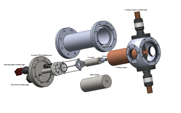
The whole oven consists of heating parts, temperature testing and control parts, supporting elements and cooling parts. Also, the core part of crucible and nozzle. Here is an exploding view from our indium oven.

Items needed
- Custom Flange feedthrough
- Thermocouples and thermocouple feedthrough
- Tantalum heating wires and current feedthrough
- Crucible and nozzle
- PBN holding rings
- Vacuum Flange, cube and viewports
- Heating wire power system
- Cooling system for oven
Crucible and Nozzle design ideas
The core part of an oven is the crucible which stores the indium. The crucible design idea comes from the reason that the SVT cell leaked. The most possible explanation for the leak is that when the indium inside the crucible was heating or cooling through the phase point, its volume will becomes bigger which will extrude the gasket which linked the crucible and its sealing ring. Therefore, we will design the crucible which firstly can contain enough pure indium and the indium liquid should be under the center nozzle position. Our design will not have the leak problem any more, because the crucible has a 5mm hole in the middle. Indium metals will be all under the lower edge of the hole. The 5 mm hole has two use: one is for loading the pure indium small ball into the crucible, the other is to plug a micro-array nozzle. But the nozzle with 5mm diameter will be too small, it should be at least 1cm. The tricky thought with the crucible front panel design was drilled the front of the crucible with 5mm depth, 10mm width hole firstly, and then, drilled 5mm width hole. Then we can plug in the 1cm nozzle! The crucible will be made with stainless 316L. To determine the size of crucible, we should know how much indium we need. We need 35g indium. Calculate the volume we need $10 cm^{3}$. Because we decided the whole oven can be fitted in a CF63 nipple and linked the nipple to the cube which will be connected with ion gauge, ion pump. So the crucible width will be small, the width of it is 12mm and length of the crucible is 7cm. The crucible will use a 316L stainless steel because that it is cheap and easy machinable. Also, it has high melting point of 1390°C which is much higher than the working temperature for our design. The mean thermal expansion coefficient from 20-1000 °C is 19.4*10^{-6} cm/(cm ^°C), which we can accept.
The nozzle width is 10mm, with length of 22mm, on one side of it should be plugged inside the crucible. There are 203 micro channel arrays with length of 1cm that designed to make the atom beam collimated.
The nozzle should work at much higher temperature (50°C higher) than the crucible to prevent the nozzle from clogging. We choose the 316L stainless steel for the fabrication of the nozzle, which is the same with the crucible to keep same thermal expansion rate when they are heated.
Heating elements
temperature test parts
Holding parts
Cooling parts for the oven
I designed a 316L stainless steel shield which is polished both inside and outside. It was connected with the stainless steel baseplate which we mentioned before by M1.6 vented screws. The shield is used for reflecting heat radiation from the heating wire onto the crucible. This idea comes from Etienne Staub's master thesis.
In the createc oven, we use water cooling method, however, the chiller is noisy and sometimes caused problem when the electricity shut down. So in this design, we will use another method. Outside the stainless steel shield, I designed a copper shield with the same shape. By linking two big copper power feedthrough (Lesker EFT0043032) with the copper shield, we can cool the oven by connecting thermoelectric cooler (TEC) with the copper feedthrough.
Oven setup
Wiring practice
Washing parts for vacuum
- We began by filling the large ultrasonic bath in the wet lab with 6x800 mL of tap water and 200 mL of Decon 90 detergent. The bath was heated to 50 C. Keep the washed stuff in the bath for 20 minutes and above.
- Next we rinsed each part with distilled water and then blew them off (for drying purposes) with the air gun in the wet lab.
- Then each part was rinsed in alcohols. The order was acetone, isopropanol, and methanol. We focused on cleaning the insides and knife edges of each part. The alcohol rinse was done by fashioning a hook to hold up each vacuum part through one of its clearance holes, and then we sprayed the solvents into each part held up by the hook.
- After the solvent rinse, we dried each part by blowing it with the air gun in the wet lab.