Electron Gun
Electron Guns have been used since the late 1940s in cathode ray tube (CRT) televisions and monitors.
The design of our electron gun can be understood through its two separate functions: electron emission and electron acceleration. Namely, to first introduce electrons into the system and then to accelerate these electrons, in a controlled manner, towards a target.
The introduction of electrons is done through thermionic emission. An electric current is passed through a filament which will then undergo Joule heating. Thermionic emission will take place once the filament is sufficiently heated. This introduces electrons into the system.
The acceleration is achieved by differentially biasing electrodes within the electron gun to create an electric field that will accelerate the electrons towards the target in a controlled manner. The last clause requires more than mere potential differences but electrostatic lenses such that the electron beam can be coaxed into a desired trajectory. Broadly, both these objectives are achieved by having an acceleration section followed by a focusing section.
Directly following thermionic emission, the electrons are subject to an accelerating potential. This accelerating potential is provided by an electrode (termed the anode) which is held at a positive potential difference from the filament. This causes electrons emitted from the filament to be accelerated towards the plate. Working in tandem with the anode is the Wenhelt Cylinder. Once accelerated past the anode, the beam is focused, again, with an Einzel lens.
These two loosely defined steps should result in an electron beam that is focused on a target. The target could be anything from a screen coated in phosphorous (to show the beam spot) to a Faraday Cup which can then be connected to a current measurement device.
Team Members
The group consists of 4 team members, listed below in alphabetical order.
- Aliki Sofia Rotelli (A0236272H)
- Lai Tian Hao (A0236351L)
- Lim En Liang, Irvin (A0173028J)
- Tan Chuan Jie (A0154805E)
Idea
There are two parts to this project. The first would be to create the electron source which seems to be done with the use of a Lenard/Crookes tube [1]. Secondly, we want to focus this electron beam into a spot with the use of a homemade magnetic lens (probably a solenoid of some form). We could perhaps perform a measurement of the focal length with respect to the magnetic field strength of the lens.
Concepts
Focusing Lens
Beam Resolution
One of the most important considerations scaling down is the Rayleigh criteria. The Rayleigh criteria relates the critical dimension (CD), or smallest feasible feature size resolvable by an optical system, to the imaging wavelength (𝜆) and numerical aperture (NA). This criteria is crucial. As a result of decreasing the critical dimension.

The Wehnelt cylinder
The Wehnhelt cylinder is a negatively biased cylinder located right after the filament. It influences the focusing of the electron beam and the electron emission from the filament. When tuned appropriately, the Wenhelt cylinder, together with the anode, aids in the emission of electrons from the filament by creating a net electric field from the attractive (to the electrons) anode and repulsive Wehnelt. Being negatively biased, the Wehnelt cylinder also acts as a convergent electrostatic lens which focuses the electron beam path from the filament to the anode.
Einzel Lens
Like the Wehnelt Cylinder, the Einzel lens is also an electrostatic lens. In this electron gun, the Einzel lens is made of three cylindrical tubes in series along the direction of the electron beam. Due to the electrostatic symmetry, the ions do not lose energy through the focusing process. In operation only the middle Einzel is actively biased (positively). The other components of the lens are held at ground potential.
Schematic of Electron gun

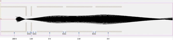
The electrical schematic is concerned with controlling the potentials of critical components. These components are the Wenhelt Cylinder, Anode and Einzel Lens. A separate distinction would be the polarity of these components. Both the Anode and Einzel lens will be positively biased up to 1kV above ground while the Wenhelt Cylinder will be negatively biased down to 1kV below ground (i.e. -1kV). These values are simply ranges and specific potential values were determined through simulations and the components were biased to recreate the conditions in these simulations.
Each of these potentials are achieved with a separate High Voltage Power Supply Unit. As will be detailed, due to the shortage of devices only two Power Supply Units were used. This was achieved by biasing both the Anode and Einzel lens to the same potentials, thus allowing one Power Supply Unit to be used for both of them. This was only possible as simulations suggested that this provided sufficient acceleration and focusing effects on the electron beam.
The actual practical set-up is more accurately depicted below.

Simulated Proof of Concept
Simulations were performed in SIMION based on a proposed arrangement of the components mentioned above.
With parameters:
- Wehnelt: -200V
- Anode: 1000V
- Middle Einzel: 500V
-
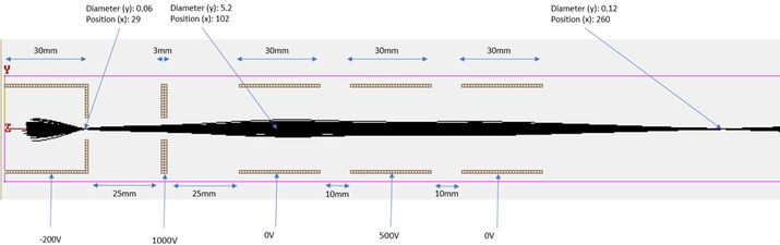
A Simulation of the focused electron beam with Wehnelt cylinder and Einzel lens (Top-Down Cross-Sectional View) -

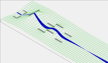
A Simulation of the focused electron beam with Wehnelt cylinder and Einzel lens (Isometric View) -
A Simulation of the focused electron beam with Wehnelt cylinder and Einzel lens (Potential Field)


These are ideal situations and in actual practical set-ups the space is constrained and all the items had to be placed closer to each other. This results in the set-ups depicted below.
-
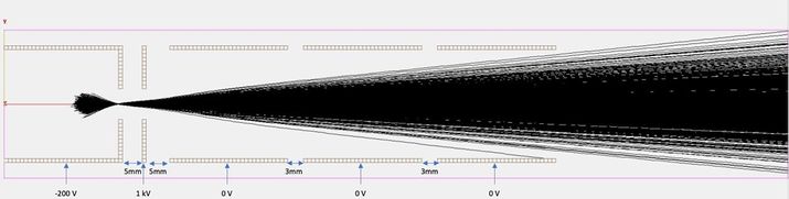
A Simulation of the revised electron gun design to account for the reduced space with Einzel lens at 0V (Top-Down Cross-Sectional View) -
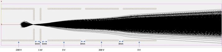
A Simulation of the revised electron gun design to account for the reduced space with Einzel lens at 200V (Top-Down Cross-Sectional View) -
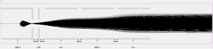
A Simulation of the revised electron gun design to account for the reduced space with Einzel lens at 400V (Top-Down Cross-Sectional View) -
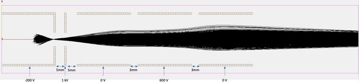
A Simulation of the revised electron gun design to account for the reduced space with Einzel lens at 600V (Top-Down Cross-Sectional View) -
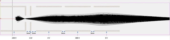
A Simulation of the revised electron gun design to account for the reduced space with Einzel lens at 800V (Top-Down Cross-Sectional View) -
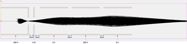
A Simulation of the revised electron gun design to account for the reduced space with Einzel lens at 900V (Top-Down Cross-Sectional View) -
A Simulation of the revised electron gun design to account for the reduced space with Einzel lens at 1kV (Top-Down Cross-Sectional View) - Wehnelt: -200V
- Anode: 1000V
- Middle Einzel: 900V to 1kV
- Acrylic plate
- Einzel lens
- Anode
- Wehnelt cylinder
- Outer diameter: 32mm
- Inner diameter: 28mm
- Length: 30mm
- Outer diameter: 32mm
- Apeture (diameter): 8mm
- Thickness: 2mm
- Outer diameter: 32mm
- Inner diameter: 28mm
- Aperture (diameter): 8mm
- Length: 30mm
- Roughing Pump
- Turbo-Molecular Pump
- 2 x PHYWE High voltage power supply with digital display; 10 kV DC: 10 kV, 2 mA
- Current Controlled PSU
- Einzel Lens
- High Vacuum Digital Gauge, with range ~ Failed to parse (SVG (MathML can be enabled via browser plugin): Invalid response ("Math extension cannot connect to Restbase.") from server "https://wikimedia.org/api/rest_v1/":): {\displaystyle 10^{-7})}
mbars
- Edwards PRM10 (Pirani Gauge)
- Edwards D145-41-000 (Penning Gauge)
- Filament (Possible choices)
- Tungsten (W) (Used in our system)
- Lanthanum Hexaboride (LaB6)
- Cerium Hexaboride (CeB6)
- Phosphors
- Zinc sulfide(ZnS) (Copper/Silver Activated)
- CF-40 Copper Gaskets
-
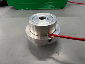
Manufactured wehnelt cylinder -
Manufactured Anode -
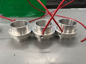
Manufactured Einzel - M5 nuts were utilized as a locking mechanism to guarantee that acrylic plates were firmly secured in place (Top and bottom of the acrylic plates).
- The wehnelt cylinder was then carefully lowed into the chamber to ensure no contact between it and the filament.
-
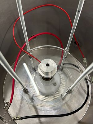
Placement of the wehnelt cylinder within the central column stack. -
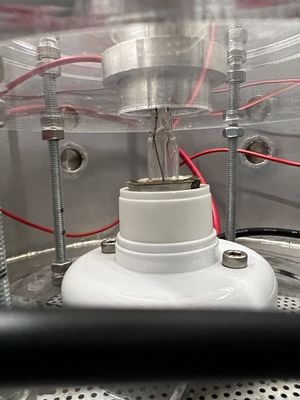
Placement of the wehnelt cylinder within the central column stack (side profile). - The rest of the components including the anode and three einzel lens were then assembled within the chamber to achieve a full stack similar to the illustration of the schematic diagram.
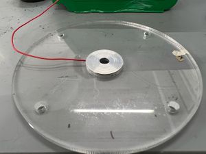
- With the central column setup completed, the phosphor was then mounted on the chamber lid with the use of Kapton tape. (Note: During the process of mounting, glass slide shattered causing a slight misalignment of the phosphor with respect to the center of the column.)
-
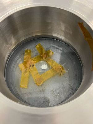
Phosphor on a microscope glass mounted on with Kapton tape (bottom side). -
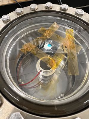
Phosphor on a microscope glass mounted on with Kapton tape (top side). -
Demonstration of checking for proper connection with a multimeter -
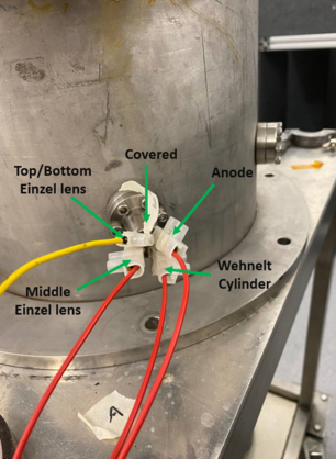
Feedthrough connections - Wehnelt cylinder potential: -200V
- Anode: 1kV
- Einzel Lens: 1kV
- Filament power supply:
- Voltage: 10V
- Current: 0.1104A


As can be seen, even with the compacting of the electron gun (placing all components closer together) a focused beam spot is still able to be produced with the following parameters:
With parameters:
Design of the electron gun's "central column"
Based on the schematic of the simulation, the development of a "central column" was designed using SOLIDWORKS, which consists of:
Acrylic Plate
The acrylic plate was created in a disk shape with a 100mm outside diameter and a 28mm inner diameter. In addition, the disk's inner ring features a 1mm by 32mm (depth/diameter) recessed on both sides. The recess was created to allow for the secure installation of subsequent elements.

Einzel lens
The three components of the Einzel was designed with dimensions:

Anode
The anode was designed with dimensions:

Wehnelt cylinder

"Central column" design

Central column with chamber design

Equipment & Components
The following items were considered for the system:
High Vacuum (HV) Components
Electrical Components
Beam Focusing Components
Measurement Components

Other Components
Setup
Manufacturing of central column
All of the items listed below were made in the workshop.
Acrylic Plate
The laser cutter is unable to make cuts at varying heights. To work around this limitation, a different approach was devised. First, a disk was cut out of a 5mm thick acrylic sheet with an outer radius of 100mm and an inner diameter of 32mm. Second, a 32mm/28mm (outer/inner) diameter ring was cut. Finally, the pieces were put together with an adhesive compound that allowed for a 1mm recess on both sides of the disk.
[Insert photo of acrylic plate]
Nine additional disks were manufactured in the same manner to obtain a total of ten disk plates.
Lathe Machine: Drilling
The three components of the Einzel lens, anode, and Wehnelt cylinder were sculpted out from a 42mm by 350mm (diameter/length) aluminum rod with the use of a lathe (a machine that rotates a workpiece about an axis of rotation to perform an operation such as cutting, sanding, drilling, etc.). After securely clamping down the aluminum rod, the rotational gears were set to “low” with a rotational speed of 105/610 rounds per minute (RPM) based on drill bit size: (Large/Small), and a drill bit secured within the “Tail Stock”.

Lathe Machine: "Facing"
After achieving the structure's inner diameter, a "facing" tool was used to remove the surface material from the outside construction, "thinning" it from 42mm to 32mm. Rotational gear was set to low-610 RPM when "facing."

Manufactured items
The following items were manufactured for the system.


Other than the manufactured items mentioned above, the filament was also prepared. The glass of the bulb was broken by lightly tapping the bulb with a metal hammer in a plastic bag. Broken glass fragments are then disposed of, resulting in the following:

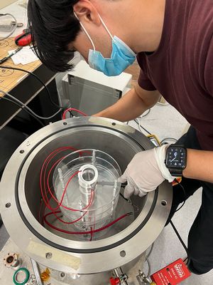
Chamber Setup
Note: Latex gloves were worn during the setup of the external ports of the chamber and the assembly of the centre column.


Fully Assembled System

Measurements/Test
Phosphor Characterization
The phosphor powder used in this project was kindly provided by Nejilock and has a composition of >99% zinc sulfide. The powder can be characterised using a fluorescent microscope. The powder is excited with UV light and the emission is collected. The spectrum of wavelengths emitted is presented in the figure below. The majority of the emission is in the 450-550 nm region, meaning the powder will have a blue/green glow.

In order to insert the phosphor powder into our system, we had to devise a way to attach it to a glass slide. The most successful method found was to create a paste by adding transparent nail polish and thinner to the powder. The paste can then be applied onto a small section of the glass slide. Once the thinner evaporates, the powder will be stuck to the glass.
Pressure Characterization
The Roughing Pump (RP) and the Turbomolecular Pump (TMP) were both characterized.
For a turbo-roughing system, a vacuum pressure of approximately Failed to parse (SVG (MathML can be enabled via browser plugin): Invalid response ("Math extension cannot connect to Restbase.") from server "https://wikimedia.org/api/rest_v1/":): {\displaystyle 10^{-3}} mbar must first be achieved using the RP before the TMP can be turned on, so as to not damage the turbine blades of the TMP.
Various pressures at different timings are recorded into the table below.
| Time | Pressure |
|---|---|
| 41 min | Failed to parse (SVG (MathML can be enabled via browser plugin): Invalid response ("Math extension cannot connect to Restbase.") from server "https://wikimedia.org/api/rest_v1/":): {\displaystyle 6.5 \times 10^{-6}} mbar |
| 16 h | Failed to parse (SVG (MathML can be enabled via browser plugin): Invalid response ("Math extension cannot connect to Restbase.") from server "https://wikimedia.org/api/rest_v1/":): {\displaystyle 1.5 \times 10^{-6}} mbar |
| 48 h | mbar |

The graphs of pressure against time for both RP and TMP were also plotted into logarithmic graphs, as shown below. The RP was transitioned into the TMP at approximately the 1064th second at a pressure of Failed to parse (SVG (MathML can be enabled via browser plugin): Invalid response ("Math extension cannot connect to Restbase.") from server "https://wikimedia.org/api/rest_v1/":): {\displaystyle 5.2 \times 10^{-3}} mbar.
 |
 |
Photos
 |
 |
 |
Conductance Test
After all of the components were assembled, conductance tests of individual components were performed to ensure proper connections between the components and the feedthroughs.


Experiment/Results
Similar to the parameters simulated:
As mentioned, because of the identical potential for the Anode and Einzel, the same power supply was able to be used for both of them while a separate one was used for the Wenhelt Cylinder.


A tinge of fluorescence can be spotted which is illuminated from the phosphor coating. With a more prominent glow located at the top right quadrant of the phosphor coating. This coincides with the slight misalignment of the glass slides during installation.

Problems and Discussion
Dim luminescence of phosphorus
When the setup was running, the glow of the phosphor was barely observed. This could be attributed to the thickness of the phosphorus and the spot size.
As mentioned previously, the spot size of the beam would be a few hundred microns. With such a spot size and a thick phosphorus layer, when the beam hits the bottom of the layer, it would illuminate only slightly. The phosphor would thus only appear to slightly "glow" and not allowing us to see the spot as expected.
Filament alignment
As the setup was built from the bottom-up and due to limitations of the size and the holder, the filament could not be adjusted freely, thereby resulting in possibilities of misaligning the filament.
After the setup was complete, it was observed that the filament was biased to one side. This would affect the results as the simulation assumes the filament to be at the centre of the Wehnelt Cylinder.
High Voltage power supplies
In the current setup, only 2 power supplies were used to vary the potential differences of the 3 Einzel lenses and the Wehnelt Cylinder. An extra power supply would enable the Einzel lens potential differences to be tuned separately, providing better fine-tuning abilities.